12V Cooling System
Scope
This project utilizes 12V DC to transfer heat from one zone to another using water and Thermoelectric Coolers. This project is a test of concept to later be used in a much larger project at a later date.
Parts List
Clicking on the parts below will take you to the Amazon site in a new tab on your browser.
Shop around for better prices than those I've linked to. For those who don't want to do so, the items I've linked in each below is what I personally used for this project.
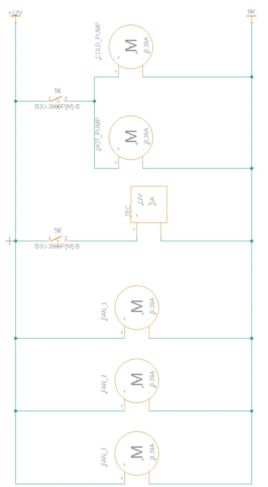
Schematics for Project
Electrical Schematic for Project
Assembly Instructions
Step 1
This step is to prep the electrical stuff for use. The power supply that is linked above has 3 terminals for the (+) and 3 terminals for the (-). We will be using all three terminals for this project. To better utilize the terminals, it will be necessary to cut the plugs off the end of both pumps and all 3 fans and strip the wires back about 1/4 inch to 3/8". They will still work just fine, if you are not comfortable with doing this, then try to find a plug that you can solder to a board and plug them in. Just ensure that the red wire on each fan and pump goes to the positive terminal (+) and the blacks go to the negative terminal (-) on the power supply.
If you want to make it look neat and tidy, getting crimp on terminal lugs for a 22 gauge or 24 gauge wire will be ideal. (I used larger lugs and thus had to fold the wires to make them work)
Step 2
In this step, we will make the preparations for the liquid parts. We will need 3 tubes for each side of the cooler. In other words, 3 tubes for hot and 3 tubes for cold. Starting at the pump, locate the directional arrows on the pump. One should be pointing into the pump and one out of the pump. For the cold side we are going to go from side pointing out of the pump to one side of the aluminum heat sink. From the other side of the heat sink to one side of the single fan radiator and then back to the pump. The reason for this is we don't want to add heat to the liquid before it has the chance to cool the air going through the radiator. We will do the same thing for the hot side with the exception that the hot side will be using the 2-fan radiator. This will complete the set up of the water system short of adding the water. We will do that later on.
Step 3
This next step will get a little messy but is not a hard one. I used a popsicle stick for this part. We just need to put a dot of the thermal compound on one of the heat sinks. Use the popsicle stick to spread it as thinly as you can over it. This will help with transferring heat from the TEC to the heat sink and thus to the water. Just note, the TEC has a hot and cold side to them. The cold side is the side the letters are on. However, if you get it backwards, don't worry it is a very simple fix. Once you have the compound added, set it down and do the other one as well. When both are done, sandwich the TEC between them and keep them as square as possible. You will want to clamp them so that they don't fall apart just don't put too much clamping force or it will break the ceramics of the TEC. Just snugged up a little is plenty, you should see the thermal compound you just added squish out the sides. You can use isopropyl alcohol to wipe it off with a rag if it bothers you too much.
Step 4
In this step, we will be filling the water system up. This can get a little tricky, but it can get done. If you have a funnel, use it. I didn't have one, so ended spilling a bit of water on my work bench. Hold the pump higher than the rest of the leg you are filling and if you can, turn the radiator upside down for now. Start pouring in the water in the hole at the top of the pump reservoir. Once it is filled, put the cap in and move the radiator around a bit to get the air to come out into the pump reservoir. Once air is out add more and repeat until filled. The other option is to run the pump for a short spell and circulate the water to "burp" the system. I installed an on and off toggle switch just for this. It is not required, so it was not included in the parts list. It does make it easier though.
Be sure to fill the other side as well.
Step 5
Now that we have water in the system, we can now hook up our electrical wiring (if you've not done so already in step 1). On the positive terminals we will attach all the red wires. I suggest twisting the fans together for one terminal. Twisting the reds of the pumps together for the second terminal and leaving the last terminal for the TEC. Do the same thing for the black wires and land them on the negative terminals. For the 120V for this, you will need to make a cable if you don't have one. What I did was take an old computer cable for a computer that is now useless and cutting the part off that goes to the computer side and leaving the pronged end. I then stripped it back and landed the black on the L and the white on the N and of course the green on the ground. If you don't have that luxury, you can get a 3 prong plug at your local hardware store and ask for some 3 conductor cable that you can use with it, or buy a short extension cord that you can cut the end off of. (Perhaps I should make this a project as well later on to keep in a project kit)
Step 6
Now is the moment of truth. You just need to plug in your power supply and get the pumps pumping and fans turning. Check back every now and then and you should see one side getting warmer and the other colder. In the section below for possible improvements you will see a few things that can be done to make this better. But don't stop there. Improve on this however you like. Change it enough to make it your own!

Possible Improvements
Overall, this was a pretty fun project to perform. It was easy to implement. This gave me a bit of insight on things that can be done to possible improve the design a bit and perhaps make it better. The first thing of note is if left to run in the same room, there will not be a huge difference in the temperature of the hot versus the cold. The reason for this was the cold system was too large. I was using almost 6 foot of tubing plus the reservoir of the pump and the volume inside the radiator. In order for the system to actually lower temperature, the entire volume of water would have to get cold quick. The TEC is only capable of removing so much heat per hour. Ambient temperature would be able to heat the water before it ever got to the radiator to transfer cold to the air going through it. This brings up the first improvement that can be made on the system. Use a smaller volume of water. This will lower the total amount of heat content required to bring the temperature of the water lower. However, this goes hand in hand with the second improvement which is insulate the cold side from ambient air.
Another thing that will also help to improve it is to reduce the size of the space being cooled. I was running this in my living room. For such a small cooler, there is no way it is pulling enough heat to overcome the heat sources in the room. If it were a small cooler, it may reduce the ambient temperature low enough which will allow the water to get colder. It will require another experiment (results will be coming, parts are on order!!).
Conclusions
This was a fun project to do. It does give a bit of information. It can also be modified in so many different applications. This is a proof-of-concept project, and the concept holds true. In most of the coolers that are seen that are 12 V DC, they use a TEC with direct air heat sinks and fans. This works very well, but I was looking to see if the concept of using liquid would also be viable. It is, with some improvements. Using different liquids can be useful as well. I was figuring water would be good since it has a specific heat that is much higher than air. In any case, I will chalk this as a successful project that has room for improvements.
Trouble Shooting Section
Fan/Pump not running
- Verify terminal connections. Red on positive and black on negative.
- Ensure power supply is turned on and plugged in, or verify the battery is not dead if one is used.
- Use a different power source if one is available to verify the pump or fan is working. If the fan works, the power supply may not be plugged in or set to correct voltages.
- If a switch was used for the project as shown in the schematic, ensure the switch is turned on. If it is turned on, verify that when on there is 0V dropped across the switch by putting a voltmeter set to DC on one side of the switch and the other lead on the other side of the switch. If you see 12V when the switch is on, the switch is bad. If 0V is seen move to next step.
- Verify output voltage of power supply by hooking a lead of a voltmeter to it and ensure you are indeed getting 12 V DC. Hook the red lead to the (+) terminal and the black lead to the (-) terminal. If you are not getting 12 V, see section on "Not receiving 12V from power supply below."
- Ensure you did not run the pump dry. If the pump was running with no water, the possibility exists that you burned the pump up and damaged the impeller or the motor or both. Check the water level of your pump and check for leaks if there was water in it but it disappeared. If it is the cold side, make sure that the water did not freeze on the cooling block. If it did, use a hair dryer or heat gun and melt it. Once the water starts flowing again, you can stop heating it.
Not receiving 12V from power supply
- Ensure the power supply is plugged in and turned on. Also ensure the correct voltage is selected for the voltage being supplied. If it is 120V then ensure 115V is selected instead of 230V.
- Connect a voltmeter to power supply. If voltage is near 12V but not quite, then adjust the voltage using a terminal screwdriver and the rheostat that is on your power supply to bring the voltage up to 12V.
- There is a possibility that one of the loads is grounded and pulling voltage down. Disconnect one load at a time and check the voltage of the output. If voltage returns, trace the load to find the short or ground that is pulling voltage down.
- If there is no ground and voltage is still not reaching 12V, cross check the model number of the power supply and verify it is capable of producing 12V.
Thermoelectric Cooler is not transferring heat or cold is actually hot and hot is cold.
- Ensure 12V is supplied to the Thermoelectric Cooler (TEC) and if any switch is used, that it is turned on.
- If voltage is present and verified to be 12V, the TEC is most likely defective. To ensure this, check the red and black wire where it attaches to the TEC block. Ensure the wires did not break at the joint which would cause it to not work. If it is broken at the joint, you can attempt to resolder it, but if not available or you are not comfortable with soldering, then replace it. If the wires are not damaged, then most likely the TEC is defective and should be replaced.
- If the cold and hot are backwards, just swap the leads. Put the black on positive and red on negative and it should reverse the hot and cold sides. If you are not comfortable with this, then swap your heat exchangers on each side of the TEC. Ensure that you have enough thermal compound for this and just remove any excess using rubbing alcohol or denatured alcohol (use proper Personal Protective Equipment if using Denatured)
I filled the line with water, but the tank went empty, or the water won't flow
- This is natural. There is air in the radiator due to how the tubing runs inside it. Just run the pump for a short burst then add more water until filled. Depending on the size of the system you decided on making, this could take a few runs to get all the air out of the system.
- If water level continues to drop, check for leaks in your system.
- If the flow stopped on the cold side, check to make sure the water did not freeze inside the cooling block. If it did freeze, melt it using a hair dryer or heat gun. For both sides, if it stopped flowing, check for blockages in the system or pinched hoses.